How to Set Up an Aluminium Scaffolding Tower
To set up an aluminium scaffolding tower, assemble it on firm level ground following the correct sequence, fit the outriggers or stabilisers, lock all castors, and add guardrails and toe boards to the working platform. Access it from inside - never the outside of the frame - and inspect the finished tower before anyone climbs.
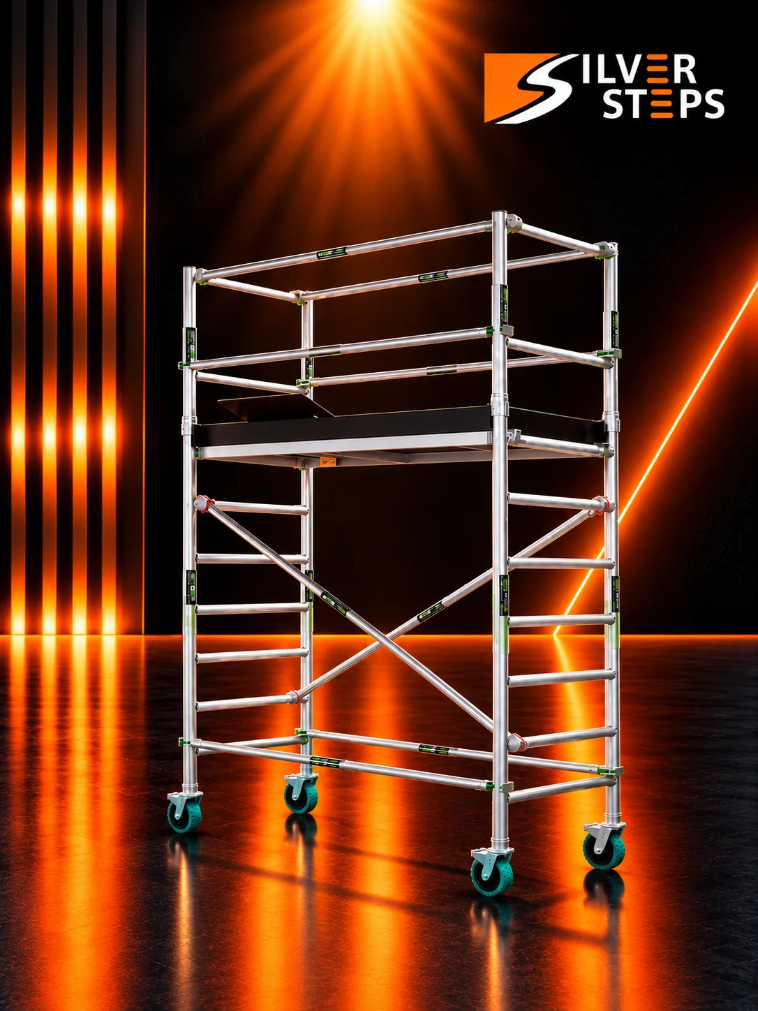
Ground Preparation & Castor Insertion
Prepare clear floor space and mount adjustable castor stems into both base ladder frames before lifting any uprights.
Stem Insertion & Collet Engagement
Slide heavy-duty polyurethane wheeled castors with threaded adjustment collars into the bottom upright stiles of the two starting end frames until retention clips snap into position.
Immediate Dual Braking
Depress the cam-lock pedals on all four castor wheels firmly with footwear to lock both rotational roll and axial swivel prior to attaching braces or standing frames upright.
Thread Height Pre-Alignment
Set each adjustable castor collar roughly midway along its thread length (approximately 75 mm to 100 mm from the base) to allow sufficient upward and downward leveling travel.
Horizontal Bracing & Base Leveling
Connect opposing base frames with color-coded horizontal braces and adjust threaded collars until bubble vials register dead center.
Low-Rung Horizontal Ties
Snap the spring-loaded claw hooks of two horizontal braces onto the lowest vertical rungs, facing claws outward. This ties both upright frames into a rigid rectangular four-sided base box.
Two-Plane Spirit Leveling
Place a spirit level across both width rungs and longitudinal braces. Spin the knurled threaded nuts on individual castors until the base sits perfectly horizontal in both X and Y axes.
Diagonal Corner Check
Measure corner-to-corner diagonal distance across the base frame with a tape measure. Equal diagonal distances confirm the structure is square, eliminating torsion stress on joints.
Diagonal Bracing & Plumb Alignment
Install opposing diagonal braces across successive rungs to create rigid shear trusses that prevent rhomboid sway.
Opposing Diagonal Cross-Pattern
Hook the first diagonal brace from rung one of frame A up to rung three of frame B. Mount the opposite brace in counter-formation from rung one of frame B to rung three of frame A.
Vertical Spigot Stacking
Slot upper extension frames onto the lower frame spigots. Ensure interlock locking clips or gravity pins automatically click into the receptor holes to lock the vertical columns together.
Plumb Line Verticality Audit
Verify vertical columns using a vertical spirit level or plumb line. Maximum allowable deviation across height must not exceed 1% or 20 mm total out-of-plumb displacement.
Through-The-Trapdoor (3T) Assembly
Climb exclusively from within the tower framework and sit through the hatch opening to erect higher guards before standing.
Trapdoor Platform Installation
Hook the intermediate trapdoor deck onto designated frame rungs. Flip the safety wind-locks located beneath each hook bracket underneath the rung to prevent uplift from thermal updrafts or wind.
Seated Guardrail Placement
Using the approved 3T method, sit through the open hatchway with your feet resting on the rungs below. Position upper guardrail braces into place before stepping onto the unprotected deck.
No External Frame Climbing
Never climb exterior horizontal braces or diagonal members. Internal integrated rung ladders or dedicated stairway towers provide designated ascending routes.
Outrigger Clamping & Footprint Expansion
Fasten telescopic outriggers at 45 degree angles to double the effective overturning resistance before extending height.
45-Degree Corner Deployment
Clamp the upper and lower coupler collars of each outrigger firmly onto the vertical stiles. Splay arms outward at 45 degree angles to form a broad geometric pyramid base.
Firm Foot Contact Adjustment
Extend the telescopic lower foot leg until the rubber base pad firmly contacts the subfloor without lifting the castor off the ground. The castor bears gravity; the outrigger stops tipping.
Height-to-Base Ratio Governance
Under EN 1004 regulations, free-standing mobile towers must not exceed a 3:1 height-to-base ratio outdoors (wind loaded) or 3.5:1 indoors. Stabilisers are compulsory above 2.5 m platform heights.
Top Working Platform, Guardrails & Toe Boards
Enclose the top deck with perimeter guardrails, intermediate knee rails, and aluminum toe boards, then run our formal scaffolding safety checklist before handover.
950 mm Perimeter Guardrail System
Mount horizontal upper guardrails at 950 mm to 1100 mm above the platform surface on all four sides. Snap intermediate knee-rails into place at 475 mm height to eliminate lateral fall gaps.
150 mm Toe Board Interlock
Drop the four-sided interlocking aluminum toe board unit into retaining clips around the entire deck perimeter. This 150 mm lip stops kicked fasteners, hand tools, or power equipment from dropping.
Pre-Climb Sign-Off & Scafftag
Before opening the tower to technicians, perform a full walkthrough verifying castor brakes, brace claws, wind-locks, and outriggers. Refer to our scaffolding safety checklist to sign off.
Summary Checklist
- Level Ground Foundation: Level ground + correct sequence
- Outrigger Deployment: outriggers deployed
- Dual Castor Brakes: castors locked
- Guardrail Enclosure: guardrails + toe boards
- Internal Trapdoor Climb: climb inside, never outside
- Key Parameter 06: inspect; never move occupied.
Mansoor Yusuf Khanani
Proprietor & Technical Director - Silver Steps (Manufacturer Since 2004)
Overseeing metal fabrication, structural aluminium alloys and dielectric fiberglass tooling at Silver Steps' Kurla West production workshop in Mumbai. Over 20 years of hands-on access equipment manufacturing, proof-load testing and industrial workplace safety compliance across India.
Common Questions
Keep Reading
Explore authoritative engineering guides, regulatory compliance standards, and access equipment rigging protocols.
Need Expert Advice on Industrial Ladders?
Speak directly with our access equipment engineers. Get exact load ratings, custom sizes, proof certificates, and wholesale factory pricing from Kurla West, Mumbai.